 Learn Metallurgy
mail@learnmetallurgy.com
Dispersion strengthening refers to the process of increasing the strength of a material by introducing uniform dispersion of second phase particles through the addition of an alloying element, which inhibits the motion of dislocations
Presence of small particles of a second phase and, if dispersed in a matrix can remarkably increase the matrix yield strength even when the dispersoid volume fraction is low. This is so because an aggregate of solute atoms resists dislocation motion to a considerably greater extent than does an isolated solute atom. The second phase particles in dispersion-hardened alloy has very little solubility in the matrix even at elevated temperature and have no coherency between the secong phase particle and matrix. hence, offer much more resistance to dislocation than precipitation hardening.
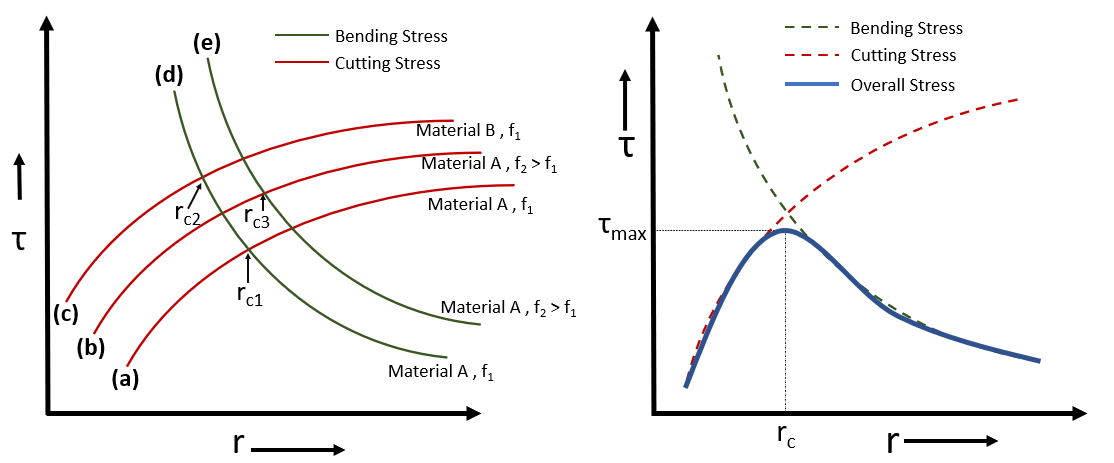
Dispersion strengthening depends on a number of factors. These include the size, volume fraction and elastic modulus of the dispersed particles. The volume fraction can also be defined in term of L, i.e., average distance between two particles. The stress required to force the dislocation through obstacles / 2nd phase partocles is -
\[ \tau = \frac{Gb}{L} \]
Here,
\( \tau \) : Stress required to bend dislocation between two particle
G : Shear modulus
b : Burger's vector
L : Distance between the particles
Closely spaced fine particles obstruct the motion of dislocations moving in the matrix. A moving dislocation has two options to pass through dispersion particles as -


 The above figure (a), show a straight dislotaction line (t) having burger vector 'b' approching to two particles seperated by distance 'L'. In figure (b), on application of stress the line beginning to bend and contineous to bend till it reaches a critical radius (fig (c)), and stress required to bow the dislocation line b/w these two particles will be - \[ \boxed{ \tau = \frac{Gb}{L} } \] After this point dislocation will start bulging out and the segments of dislocation will meet (or annihilate, as dislocations will be of opposite sign on other side) on other side of the particle. leaving a dislocation loop around each particle (fig. (d)). And then continues to move ahead as shown in figure (e).
