 Learn Metallurgy
mail@learnmetallurgy.com
 Slip System : The combination of slip plane and slip direction.
 | Crystal | Metals | Slip Plane | Slip Direction | Number of Slip System |
|---|---|---|---|---|
| FCC | Cu, Al, Ni, Ag, Au | {111} | <110> | 12 |
| BCC | α-Fe, W, Mo | {110} | <111> | 12 |
| α-Fe, W | {211} | <111> | 12 | |
| α-Fe, K | {321} | <111> | 24 | |
| HCP | Cd, Zn, Mg, Ti, Be | {0001} | \( <11\bar{2}0> \) | 3 |
| Ti, Mg, Zr | {\( {10\bar{1}0} \)} | \( <11\bar{2}0> \) | 3 | |
| Ti, Mg | {\( {10\bar{1}1} \)} | \( <11\bar{2}0> \) | 6 |
 • The above image show a SIMULTANEOUS BOND BREAKING MODEL.
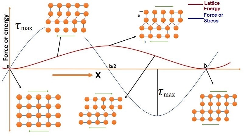 From Above fig. the first approximation of realtionship between shear stress and displacement can be expressed by sine function as -
\[ \tau = \tau_{max} \big(sin \frac{2\pi x}{b} \big) \]
For maimum shear stress x=a, and for small value of a/b the above equation can be written as -
\[ \tau = \tau_{max} \Big(\frac{2\pi a}{b} \Big) \]
As for rough approximation b = a, and also as \( \tau = G\gamma \)
\[ \boxed{ \Rightarrow \tau_{max} = \frac{G}{2\pi} } \]
Where \( \tau_{max} \) = Theoratical shear strength, and G = Shear Modulus.
From Above fig. the first approximation of realtionship between shear stress and displacement can be expressed by sine function as -
\[ \tau = \tau_{max} \big(sin \frac{2\pi x}{b} \big) \]
For maimum shear stress x=a, and for small value of a/b the above equation can be written as -
\[ \tau = \tau_{max} \Big(\frac{2\pi a}{b} \Big) \]
As for rough approximation b = a, and also as \( \tau = G\gamma \)
\[ \boxed{ \Rightarrow \tau_{max} = \frac{G}{2\pi} } \]
Where \( \tau_{max} \) = Theoratical shear strength, and G = Shear Modulus.
• The movement of dislocation is related with the Caterpillar Movement
• In this model we only move planes bit by bit instead of whole plane at once. which reduces the shear stress required to slip.
• This model was introduced by peierls nabarro and the steess predicted by this model is called as peierls nabarro stress or lattice friction.
• He also introduce a fact that dislocation has a width. The width of the dislocation is the distance on either side of dislocation upto with dislocation stess is applicable.
• Narrow dislocation are difficult to move.
\[ \boxed{ \tau_{PN} = \frac{2G}{1-\nu} exp{\Big(- \frac{2\pi w}{b} \Big)}} \]
Where w = Width of dislocation, and \(w = \frac{a}{1-\nu} \), a= inter-planer spacing
Important Points :
(1) For CPP \( a \uparrow \Rightarrow w \uparrow \Rightarrow \tau_{PN} \downarrow \Rightarrow \) Stress required for slip is less means ductile material.
(2) Slip will occure when \( \tau_{PN} \) is less , means slip will occure in Closed pack plane ( i.e., \( a \uparrow \) ) and closed pack direction \( b \downarrow \)
(3) In covalent crystal dislocation width(w) is very less => Difficult to move dislocation => brittle
(4) For ionic crystal, moderate value of \( \tau_{PN} \) is required. But brittle frature is observed due to large 'b'.

P = Applied Load
N = Slip plane normal
D = Slip DIrection
\( \lambda \) = Angle between P & N
\( \phi \) = Angle between P & D
\[ \tau_{RSS} = \frac{P}{A} = \frac{Fcos(\phi)}{\frac{A}{cos(\phi)}} \]
\[ \Rightarrow \tau_{RSS} = \sigma cos(\lambda) cos(\phi) \]
Special Cases :
(1) If \( \lambda = 90 \Rightarrow cos(\lambda) = 0\) => \( \tau_{RSS} = 0 \)
(2) If \( \phi = 90 \Rightarrow cos(\phi) = 0\) => \( \tau_{RSS} = 0 \)
Critical Resolved Shear Stress (\( \tau_{CRSS} \)) :
Slip in a material occures when the shearing stress on the slip plane in the slip direction reaches a threshold value called the critical resolved shear stress.
Where \( cos(\lambda) cos(\phi) \) is called as Schmid Factor and \( \sigma_{y} =\) Yield Strength
Note :
(1) If we change the direction of stress w.r.t. slip plane and slip direction, \( cos(\lambda) cos(\phi) \) will also change but \( \tau_{CRSS} \) will not change. Hance \( \sigma_{y} \) will change => \( \sigma_{y} \) is anisotropy in nature.
(2) \( \tau_{CRSS} \) is a material property.
(3) Slip system with higher Schmid factor will be active slip system.
Condition For Dislocation Motion
\[ \tau_{RSS} > \tau_{CRSS} \]
LearnMetallurgy.com is dedicated to providing you unique and in-depth knowledge of the Metallurgical world. We regularly post blogs related to metallurgical field,jobs updates, and Provide Free Speed Test for GATE and PSUs.
Bengaluru, Karnataka
mail@learnmetallurgy.com
© 2021. All Rights Reserved. Sitemap Privacy Policy Term And Conditions Cancellation and Refund Policy